How to Draw a Rench in Autocad
Introduction to AutoCAD Tools
Various components of the basic AutoCAD screen are the menu bar, drawing area, several toolbars, command window, model and layout tabs and status bar. The title bar has an AutoCAD symbol, and the current drawing name is displayed on top of the screen. The various AutoCAD tools present to assist in drawing a certain part/component, the most basic types used are:
- Line
- Circle
- Rectangle
- Polyline
- Trim
- Extend
- Copy
- Mirror
- Rotate
- Erase
- Offset
- Move
- Array
- Scale
- Fillet
- Explode
Various AutoCAD Tools
Here are the various AutoCAD Tools which are given below
1. Line
You can invoke the LINE command by choosing the LINE tool from the Draw panel, or you can also invoke the LINE tool by entering LINE or L at the Command Prompt. You will have to specify the starting point of the line by clicking the mouse then you will be prompted to specify the second point. You can terminate the LINE command by pressing ENTER, ESC or SPACEBAR.
2. Circle
A circle is drawn by using the CIRCLE command. You can draw a circle by using six different tools, i.e., by specifying center and radius, by specifying center and diameter, by specifying two diametrical ends, by specifying three points on a circle, tangent to two objects, tangent to three objects.
3. Rectangle
You can draw rectangles by specifying two opposite corners of the rectangle, specifying the area and the size of one of the sides, or specifying the rectangle's dimensions.
4. Polyline
Polylines means many lines. To draw a polyline, you need to invoke the PLINE command. After invoking the PLINE command and specifying the start point, the following prompt is displayed:
Specify start point: specify the starting point or enter its coordinates
Current line width is: nn.nnnn(00.0000)
Specify next point or [Arc/Halfwidth/Length/Undo/Width]: specify the endpoint of the first polyline segment.
Specify next point or [Arc/Close/Halfwidth/Length/Undo/Width]: specify the endpoint of the second polyline segment or press ENTER to exit the command.
5. Trim
When creating a design, you may need to remove the unwanted and extending edge. In such cases, you can use the Trim tool. On invoking the Trim tool, you will be prompted to select the cutting edges. These edges can be lines, polylines, circles, arcs, ellipses, rays, splines, text, blocks, xlines or even viewports. After the cutting edge/edges are selected, you must select each object to be trimmed.
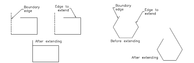
6. Extend
The Extend tool may be considered as the opposite of the Trim tool. You can extend lines, polylines, rays, and arcs to meet the other objects using the Extend tool. You can use this option whenever you want to extend the objects that do not actually intersect the boundary edge but would intersect its edge if the boundary edges were extended.
7. Copy
This tool is used to make the copies of the selected objects and place them at the specified location. On invoking this tool, you need to select the objects and then specify the base point. Next, you need to specify the second point where the copied objects have to be placed. You can continue specifying the second point for creating multiple copies of the selected entities.
8. Mirror
This tool is used to create a mirror copy of the selected objects. The objects can be mirrored at any angle. This tool is helpful in drawing symmetrical figures. On invoking this tool, you will be prompted to select objects. On selecting objects to be mirrored, you will be prompted to enter the first point of the mirror line and the second point of the mirror line. A mirror line is an imaginary line about which the objects are mirrored.
9. Rotate
On invoking this tool, you will be prompted to select the objects and the base point about which the selected objects will be rotated. By default, a positive angle results in counterclockwise rotation, whereas a negative angle results in a clockwise rotation. The Rotate tool can also be invoked from the shortcut menu by selecting an object and right-clicking in the drawing area, and choosing Rotate from the shortcut menu.
10. Erase
Sometimes, you need to erase the unwanted objects from the objects drawn. To erase an object, choose Erase tool from the Modify panel. To invoke the Modify toolbar, choose View>Windows>Toolbars>AutoCAD>Modify from the ribbon. A small box, known as a pick box, replaces the screen cursor on invoking the Erase tool. To erase the object, select it by using the pick box; the selected object will be displayed in dashed lines, and the Select objects prompt will be displayed again. You can either continue selecting the objects or press ENTER to terminate the object selection process and erase the selected objects.
11. Offset
You can use the Offset tool to draw parallel lines, polylines, concentric circles, arcs, curves, etc., While offsetting an object, you need to specify the offset distance and the side to offset.
12. Move
The Move Tool is used to move one or more objects from their current location to a new location without changing their size or orientation.
13. Array
You may need to create an object multiple times in a rectangular or circular arrangement in some cases. This type of arrangement can be obtained by creating an array of objects. In Rectangular Array, you need to mention the number of rows and columns along with the Row offset distance and Column offset distance. Whereas in Polar Array, you need to specify the Center point around which you need the number of objects.
14. Scale
Sometimes you need to change the size of objects in a drawing. For this purpose, the Scale tool comes in handy.
15. Fillet
The edges in a model are generally filleted to reduce the area of stress concentration. The fillet tool helps form round corners between any two entities that form a sharp vertex.
16. Explode
This tool is useful when you have inserted an entire drawing, and you need to alter a small detail. After you invoke the Explode tool, you are prompted to select the objects you want to explode. After selecting the objects, press ENTER or right-click to explode the selected objects and then end the command.
Conclusion
Thus, we have seen that a drawing can be drawn and further modified from the above-mentioned tools, scaled, copied. These tools help us in major operations of drawing using AutoCAD software. Apart from these, we can further color the line with a specific line type and line weight.
Recommended Articles
This is a guide to AutoCAD Tools. Here we have discuss the various AutoCAD tools present to assist in drawing a certain part/component. You may also look at the following article to learn more –
- Adobe Photoshop Tools
- Install AutoCAD
- Advantages Of AutoCAD
- AutoCAD Architecture
Source: https://www.educba.com/autocad-tools/
0 Response to "How to Draw a Rench in Autocad"
Post a Comment